


- Sulfuric Acid Flow Meter Selection Guide (Part 1)
Sulfuric acid, as the "mother of industries", requires precise flow measurement for the stable operation of its equipment. However, in the face of the strong corrosiveness, high viscosity, and complex working conditions of sulfuric acid, choosing the right flowmeter often poses a headache for instrument technicians. This magazine will continuously release the "Sulfuric Acid Flowmeter Selection Guide" in two parts. This week, the upper part will introduce you to the four commonly used types of flowmeters: electromagnetic, mass, ultrasonic, and orifice plate, and deeply analyze their working principles to lay a solid foundation for subsequent precise selection. Full of valuable content, please save and read slowly!
I. Overview
In the sulfuric acid production plant, accurate measurement of the sulfuric acid flow rate is a crucial step for ensuring the stable operation of the plant, optimizing the production process, and enhancing economic benefits. Sulfuric acid has characteristics such as strong corrosiveness, high density, high viscosity, and significant differences in conductivity at different concentrations, which pose many challenges for flow measurement. The operating conditions at different measurement points (such as acid concentration, temperature, pressure, pipe diameter, etc.) vary greatly, so it is necessary to select the appropriate type of flowmeter based on the specific conditions to ensure the accuracy and reliability of the measurement.
This guide aims to systematically review the common types of flow meters used in the sulfuric acid production process, analyze their working principles and applicability, and, based on the actual operating conditions of each measurement point in the sulfuric acid production facility, provide scientifically reasonable selection recommendations to offer technical reference for the selection of instruments by sulfuric acid production enterprises.
II. Several Common Flowmeters for Sulfuric Acid Measurement
In the sulfuric acid production plant, the commonly used types of flow meters include electromagnetic flow meters, mass flow meters, ultrasonic flow meters and orifice plate flow meters. Each type of flow meter has its own unique working principle, technical characteristics and application scope. When selecting the flow meter in practice, factors such as the properties of the measured medium, process conditions and measurement requirements need to be comprehensively considered.
2.1 Electromagnetic Flowmeter
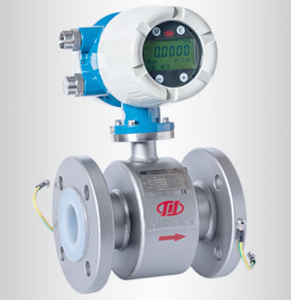
The electromagnetic flowmeter is a velocity-type flowmeter that operates based on Faraday's law of electromagnetic induction. It consists of two parts: a sensor and a converter. The sensor is installed on the measuring pipeline, while the converter is used to process and display the flow signal.
The main features of the electromagnetic flowmeter include: the measurement is not affected by changes in fluid density, viscosity, temperature, pressure and electrical conductivity; there are no obstructive components in the measuring tube, no pressure loss, and lower requirements for straight pipe sections; the output signal has a linear relationship with the flow rate, with high measurement accuracy, reaching ±0.5%; the measurement range ratio is wide, up to 100:1 or more. It is suitable for measuring volumetric flow of dry acids, absorbent acids, etc. at various positions. In sulfuric acid plants, electromagnetic flowmeters are widely used to measure points such as drying circulating acid, secondary absorption circulating acid, secondary acid, HRS acid production acid, etc. When selecting, special attention should be paid to choosing the appropriate lining and the corrosion resistance of the electrode materials for the acid temperature.
2.2 Mass Flowmeter
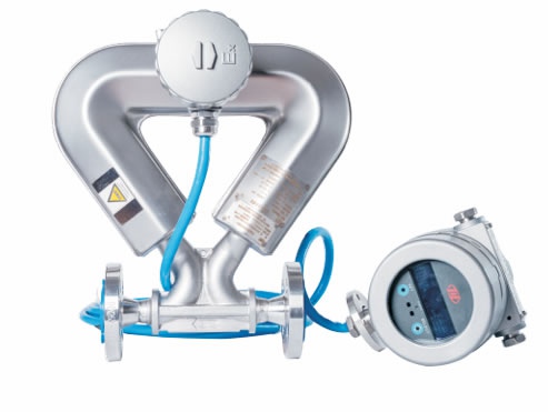
The mass flowmeter (mainly referring to the Coriolis mass flowmeter) is a highly accurate instrument that directly measures the mass flow rate of fluids. It utilizes the Coriolis effect generated when fluids flow through the vibrating tube, and calculates the mass flow rate by detecting the phase difference of the vibrating tube.
The main advantages of the mass flowmeter are as follows: it directly measures the mass flow without the need for temperature and pressure compensation; the measurement accuracy is extremely high, reaching ±0.1% to ±0.2%; it can simultaneously measure parameters such as density and temperature; it is not affected by changes in fluid physical properties. It is particularly suitable for occasions with extremely high precision requirements, such as trade settlement, acid production in the device, and acid loading for finished products.
The limitations of the mass flowmeter are as follows: it is expensive; it has strict installation requirements and must avoid vibration interference. In the sulfuric acid plant, it is mainly used for trade metering of finished acid and sulfuric acid for export loading, as well as for the trade metering of raw acid entering the plant.
2.3 Ultrasonic Flowmeter
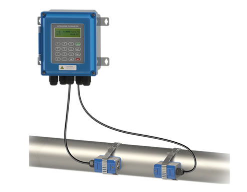
An ultrasonic flowmeter is an instrument that measures the flow rate by using the time difference or frequency difference of ultrasonic waves propagating in the fluid. According to the installation method, it can be divided into external clamp type and insertion type. According to the measurement principle, it can be classified as time difference method, Doppler method, etc.
The main features of the ultrasonic flowmeter: non-contact measurement (external clamp type), without damaging the pipeline integrity, and without pressure loss; easy installation and maintenance, can be installed without stopping production; suitable for measuring large-diameter pipelines; not affected by the medium's conductivity, can measure low-concentration or low-conductivity sulfuric acid media.
The limitations of ultrasonic flowmeters are as follows: They are sensitive to the condition of the pipe inner wall, and scaling will affect the measurement accuracy; the time difference method requires a moderate amount of solid particles or bubbles in the fluid; the measurement accuracy is relatively low (generally ±1% to ±2%). In the sulfuric acid plant, ultrasonic flowmeters are particularly suitable for measuring the first-stage acid and other high-temperature and high-concentration sulfuric acid in the waste heat recovery system.
2.4 Orifice Plate Flowmeter
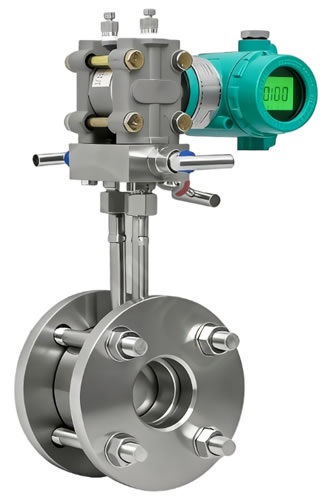
The orifice plate flowmeter is the most commonly used type of differential pressure flowmeter. It generates differential pressure by installing a throttling device (orifice plate) in the pipeline. The flow rate is calculated based on the relationship between the differential pressure and the flow rate. It has the advantages of simple structure, mature technology, and low cost.
The main features of the orifice plate flowmeter: Simple structure, no moving parts, high reliability; High standardization degree, with international standards and calculation specifications; Suitable for high-temperature, high-pressure, and corrosive media; Rich experience in use, easy maintenance.
The disadvantages of orifice plate flowmeters are as follows: significant pressure loss, high energy consumption during long-term operation; narrow measurement range (with a ratio of approximately 3:1 to 5:1); long requirements for straight pipe sections (usually needing 10D in the front and 5D at the back); and large impact of installation conditions on accuracy. In sulfuric acid plants, orifice plate flowmeters are still used in some old installations and specific high-temperature and high-pressure scenarios.
III. Working Principles of Various Flow Meters
3.1 Working Principle of Electromagnetic Flowmeter
The working principle of an electromagnetic flowmeter is based on Faraday's law of electromagnetic induction. When a conductive liquid moves through a magnetic field and cuts the magnetic field lines, an induced electromotive force is generated on the electrodes perpendicular to both the magnetic field and the flow direction. The magnitude of this induced electromotive force is proportional to the flow velocity of the fluid.
Let the inner diameter of the pipe be D, the magnetic induction intensity be B, and the average flow velocity of the fluid be v. Then the induced electromotive force E can be expressed as:
E = k · B · D · v
In the formula, k represents the instrument constant. Since the cross-sectional area A of the pipeline = πD²/4 is a known quantity and the volumetric flow rate Q = A · v, the volumetric flow rate can be calculated by measuring the induced electromotive force E. The converter amplifies, filters, and performs A/D conversion on the induced electromotive force signal, and then outputs a standard signal (4-20mA or pulse signal) proportional to the flow rate.
The inner liner insulation material of the measurement tube of the electromagnetic flowmeter sensor (such as PTFE, PFA, ceramics, etc.) is usually made of corrosion-resistant precious metals or alloy materials (such as platinum-iridium alloy, Hastelloy alloy, tantalum, etc.). The excitation methods include direct current excitation, alternating current excitation, and rectangular wave excitation, etc. Most modern electromagnetic flowmeters adopt low-frequency rectangular wave excitation to reduce polarization effects and zero drift.
3.2 Working Principle of Mass Flowmeter
The working principle of the Coriolis mass flowmeter is based on the Coriolis effect. When a fluid flows through a vibrating U-shaped tube (or a measuring tube of other geometric shapes), the fluid is subjected to the Coriolis force, causing the measuring tube to undergo torsional deformation. The mass flow is determined by detecting the phase difference between the inlet and outlet sections of the measuring tube.
During the vibration process of the measuring tube, when there is no fluid flow, the measuring tube vibrates symmetrically and the detection signals at the inlet and outlet are in phase; when fluid flows through, the Coriolis force causes the measuring tube to undergo additional torsional vibration, and a phase difference is generated between the detection signals of the inlet and outlet sensors. This phase difference is proportional to the mass flow rate of the fluid.
The mass flowmeter can also measure the density of the fluid simultaneously. The natural frequency of the measuring tube changes with the variation of the fluid density inside the tube. By detecting the vibration frequency, the fluid density can be calculated. Combined with temperature measurement, the mass flowmeter can provide multiple parameters such as mass flow, volume flow, density, and temperature.
The core component of the Coriolis mass flowmeter is the measuring tube, which is typically made of corrosion-resistant materials such as stainless steel and Hastelloy. For the measurement of sulfuric acid, the appropriate material and protective coating for the measuring tube should be selected based on the concentration and temperature of the sulfuric acid.
3.3 Working Principle of Ultrasonic Flowmeter
The working principle of the time difference ultrasonic flowmeter is to measure the flow rate by utilizing the time difference between the forward and backward propagation of ultrasonic waves in the fluid. A pair (or multiple pairs) of ultrasonic transducers are installed on the pipeline, alternately emitting and receiving ultrasonic wave signals.
Let the propagation speed of ultrasonic waves in a stationary fluid be c, the flow velocity of the fluid be v, the length of the channel be L, and the angle between the propagation direction of the ultrasonic wave and the flow direction of the fluid be θ. Then the time t₁ for propagation in the downstream direction and the time t₂ for propagation in the upstream direction are respectively:
t₁ = L / (c + v·cosθ) t₂ = L / (c - v·cosθ)
The time difference Δt = t₂ - t₁ ≈ 2Lv·cosθ / c². From this, the fluid flow velocity v can be calculated, and then the volumetric flow rate can be obtained.
The transducer of the external-mounted ultrasonic flowmeter is installed on the outer wall of the pipeline, and ultrasonic waves propagate through the pipe wall and the fluid. The transducer of the insert-type ultrasonic flowmeter is directly inserted into the fluid, resulting in a shorter signal propagation path and higher accuracy. Modern ultrasonic flowmeters mostly adopt multi-channel designs. By averaging the measurement results of different channels, the measurement accuracy and anti-interference ability are improved.
3.4 Working Principle of Orifice Plate Flowmeter
The working principle of the orifice plate flowmeter is based on the Bernoulli equation and the continuity equation. When the fluid flows through the throttling device (orifice plate) in the pipeline, the flow beam contracts, the flow velocity increases, and the static pressure decreases. A static pressure difference (pressure differential) is generated before and after the orifice plate. This pressure differential is proportional to the square of the flow rate.
The relationship between volumetric flow rate Q and differential pressure Δp is:
Q = C · ε · A₀ · √(2Δp/ρ)
In the formula, C represents the outflow coefficient, ε is the expansibility coefficient (for liquids, it is taken as 1), A₀ is the opening area of the orifice plate, and ρ is the density of the fluid. The outflow coefficient C is determined through experiments and is related to the geometric parameters of the orifice plate, the Reynolds number of the pipeline, and other factors.
The standardization level of orifice plate flowmeters is very high. Standards such as ISO 5167 and GB/T 2624 have detailed regulations on the structural dimensions, pressure tapping methods, and installation requirements of orifice plates. The accuracy of standard orifice plates can reach ±0.5% to ±1.0%, but this is subject to the conditions stipulated in the standards, such as the length of straight pipe sections and pipe roughness.
When using orifice plate flowmeters in the sulfuric acid plant, the material of the orifice plate should be selected from those that are resistant to sulfuric acid corrosion (such as Hastelloy C, tantalum, etc.), and the wear and corrosion of the orifice plate should be checked regularly to ensure the measurement accuracy.
This is the complete content of the first part of this issue. We have thoroughly analyzed the "temperament" and working principles of four mainstream flow meters. Knowing what they are is not enough; we must also understand why they behave the way they do. Only by understanding the principles can we operate them proficiently in practical applications.
However, merely understanding the principles is not enough. How can these instruments be precisely matched to specific positions such as drying towers, absorption towers, and waste heat recovery systems? What should be done when encountering difficult problems like inaccurate readings on the instruments or sulfuric acid leakage on-site? In the next article, we will focus on the adaptation to actual working conditions, troubleshooting common faults, and final selection recommendations. Please keep following us! If you have encountered typical flowmeter failure cases on-site, please feel free to leave a comment in the area to share.